There is nothing permanent except change.
—Heraclitus
thingSoC has a new, but simple method for determining the multiplexing of Input/Output Pins
for add-on boards and peripherals. Remember that the Linux Device Tree pin multiplexing information is
provided to control the pin multiplexing on the CPU or microcontroller itself; and doesn't necessarily specify
all the information about a specific peripheral pin multiplexing or it's capabilities.
thingSoC has a few simple bus
configurations that make interfacing peripherals a snap.
thingSoC Pin Configurations
thingSoC is different from the other 'lil microprocessor boards out there, such as the Arduino Mini, NXP mBed, Teensy, and others; it has defined pin configurations that are cross-platform compatible. In other words, all thingSoC compatible boards use an interchangeable interconnection scheme, even if the embedded microprocessor is a different make or model. The example below shows how this is possible :

Most Microprocessor busses, such as SPI, or I2S audio, have a grouping of particular signals that are needed to implement that particular bus type. The thingSoC specification requires those signal groupings on specific pins, so the particular signals you need, are always located where you need them to be. This insures interoperability across a wide range of peripherals and add-on boards.
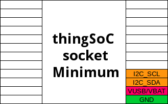
thingSoC Minimum Pin Configuration
The minimum thingSoC socket configuration is only four (4) pins, namely, Power(5V), Ground, I2C_SDA, and I2C_SCL. This allows the thingSoC socket controller to read the socket configuration information (at I2C Address 0x54 - 0x57), in order to determine how a programmable thingSoC socket is configured.

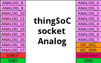
Once the thingSoC socket controller reads the socket configuration table via the I2C interface, it can configure the remainder of the socket connections corrrectly for the specific attached peripheral. For example, in an configuration that requires a large number of analog sensor inputs to be sampled, all the remaining pins might be configured to be Analog inputs, as the following example shows :

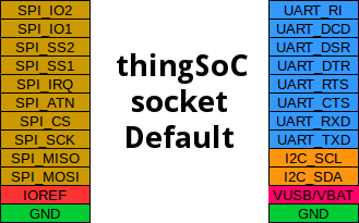
thingSoC Default Pin Configuration
The thingSoC socket default configuration is shown below, and includes, one I2C interace (minimum), one full UART interface (eight pins), one extended SPI interface (ten pins), and JTAG/Programming interface (eight pins).

The thingSoC socket pin configurations are one of the features of the thingSoC architecture that allow for simple operation and great interoperability between different microprocessor makes and models. In the next article, we'll cover the thingSoC socket extended SPI interface, capable of supporting four (4) peripherals with extra control signals.
thingSoC Resources
thingSoC defines a physical, hardware socket system for inter-operable printed circuit boards, with a data centric firmware model for automatic device discovery, and a software API for interacting with the system.
- thingSoC Project Page
- thingSoC Specification (Draft)
- thingSoC on Github
- FAQ - Frequently Asked Questions
- Arch - Hardware Overview
- Arch - Firmware Overview
- Arch - Software Overview
- Wiki - Project Wiki
- Bugs - Project Issue/Bug Tracking
thingSoC Reference Designs
- thingSoC ESP8266 Wi-Fi Reference Design
- thingSoC USBUART Reference Design
- thingSoC Cortex-M0 Reference Design
Donate
thingSoC is community supported, you can help by contributing.
thingSoC has been designed to address many of the issues and limitations with current IoT development platforms. It is a community sponsored, open source project, with no fees or licensing costs.